Controller for the linear power amplifier, version 4.0, RF detector
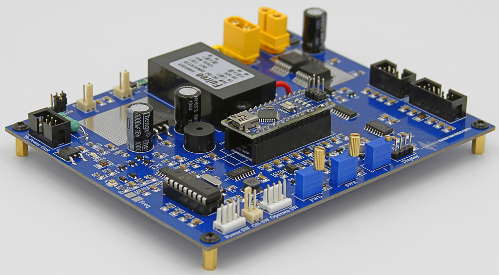
Controller designed for Amateur Radio LDMOS Amplifiers built at home. Based on powerful firmware on board Arduino Nano, it shows precise measurements, delivery voltage sequences,
all protections for LDMOS devices, touch screen switch controls and functions. It also incorporates the Rf Band Decoder that selects the Low Pass Filter automatically without additional cables.
Dimension: 148mm*120mm*20mm
Technical data
RF Band decoder 1.8 - 54 MHz | Fan Speed Controller Auto/Manual (No PWM) |
Nextion dysplay controller | SWR, Power output, drain voltage, drain current, Temperature. METERS |
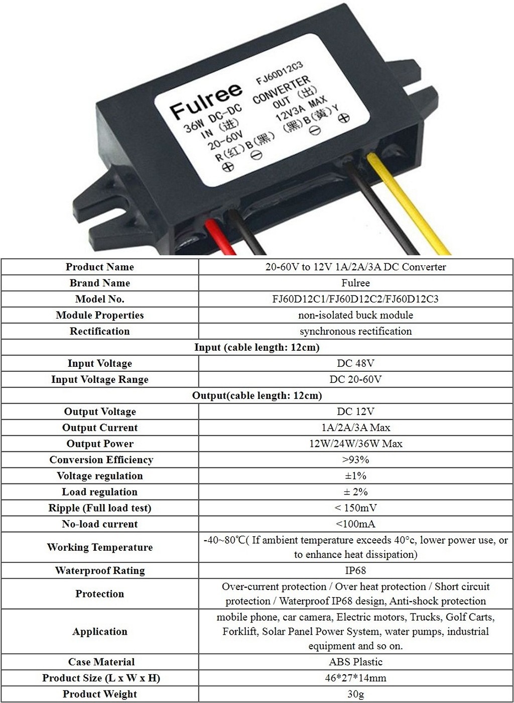
Fulree FJ60D12C3 Step down 53v - 12v | Continuous Carrier >xxx-Watt protection |
BTS 50085 50-60V 40A Solid-State Swith | Sound Alarm 800 Hz |
Antenna Relay/Bias sequencer (20 Ms) | Antenna Switch/LPF relay drivers (80 mA) |
DS18B Temperature Sensor Controller with protection | Protection of incorrect band selection |
RF Band Decoder
Is one of the most attractive options . No more incidents by forgetting or not changing the band selector.
You do not need to find the specific radio interface for amplifier tracking. Video
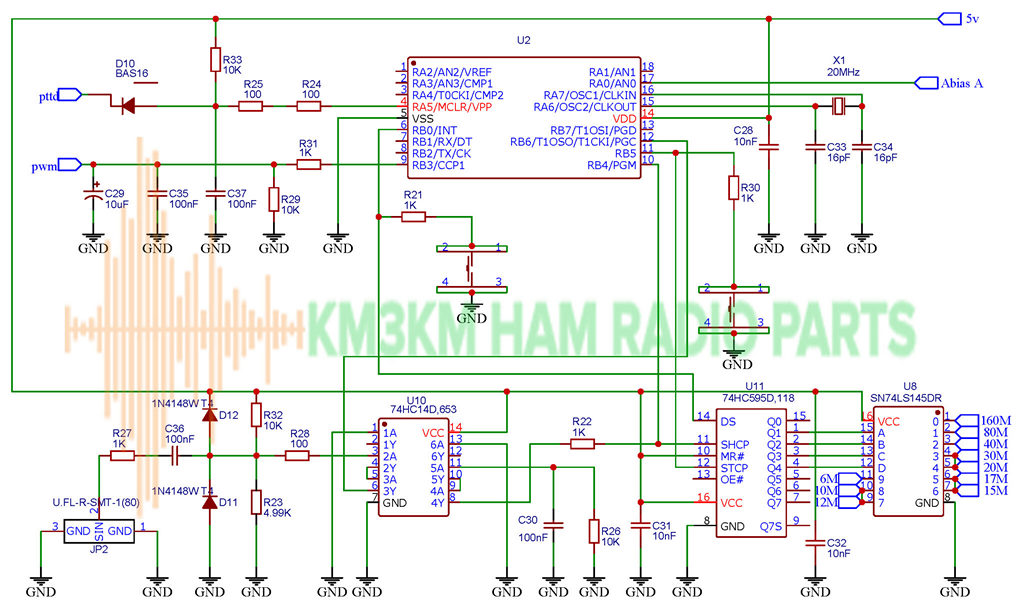
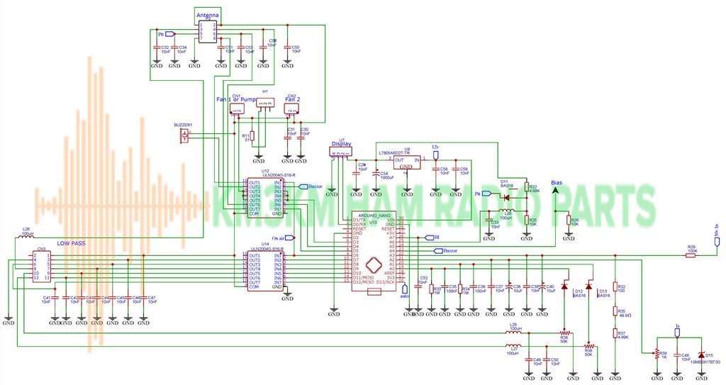
Circuit for Arduino Nano integrated in the controller
Protections for LDMOS devices
High temperature, High current, High voltage, High output power.
High SWR. LDMOS devices are usually very robust and support SWR 65:1 such as BLF188XR / MRF1K50H. But this is not enough to extend the life of the linear amplifier for Ham Radio since some components can overheat and break. Or worse, we forget to select or connect the antenna. The video shows the precise protection when SWR>2 Video
Continuous carrier detector. Some amplifier designs can withstand long cycles with an output of 1300 watts in SSB. But a continuous carrier requires twice the effort. Additional heat sink, huge ferrite cores and duplicate components, this increases the cost of home manufacturing. The video shows a protection for continuous carrier >8 seconds >700 watts. Video
Wrong Band Selection. Operating an amplifier in attenuation frequency can be fatal. The video shows the protection when the 80 meter filter is selected manually while the radio is operating at 40 meters. In addition, protection is also activated if the Low Pass Filter is damaged. This function does not need a SWR meter at the filter inlet. Video
All protections were tested and guaranteed with genuine components, never tested with fake components.
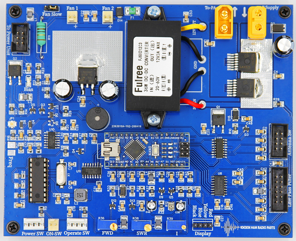
FJ60D12C3
The nominal voltage of the controller is 53v and does not need a separate 12v source. The controller incorporates a Step Down 60v-12v DC Fulree FJ60D12C3 3 Amp device:
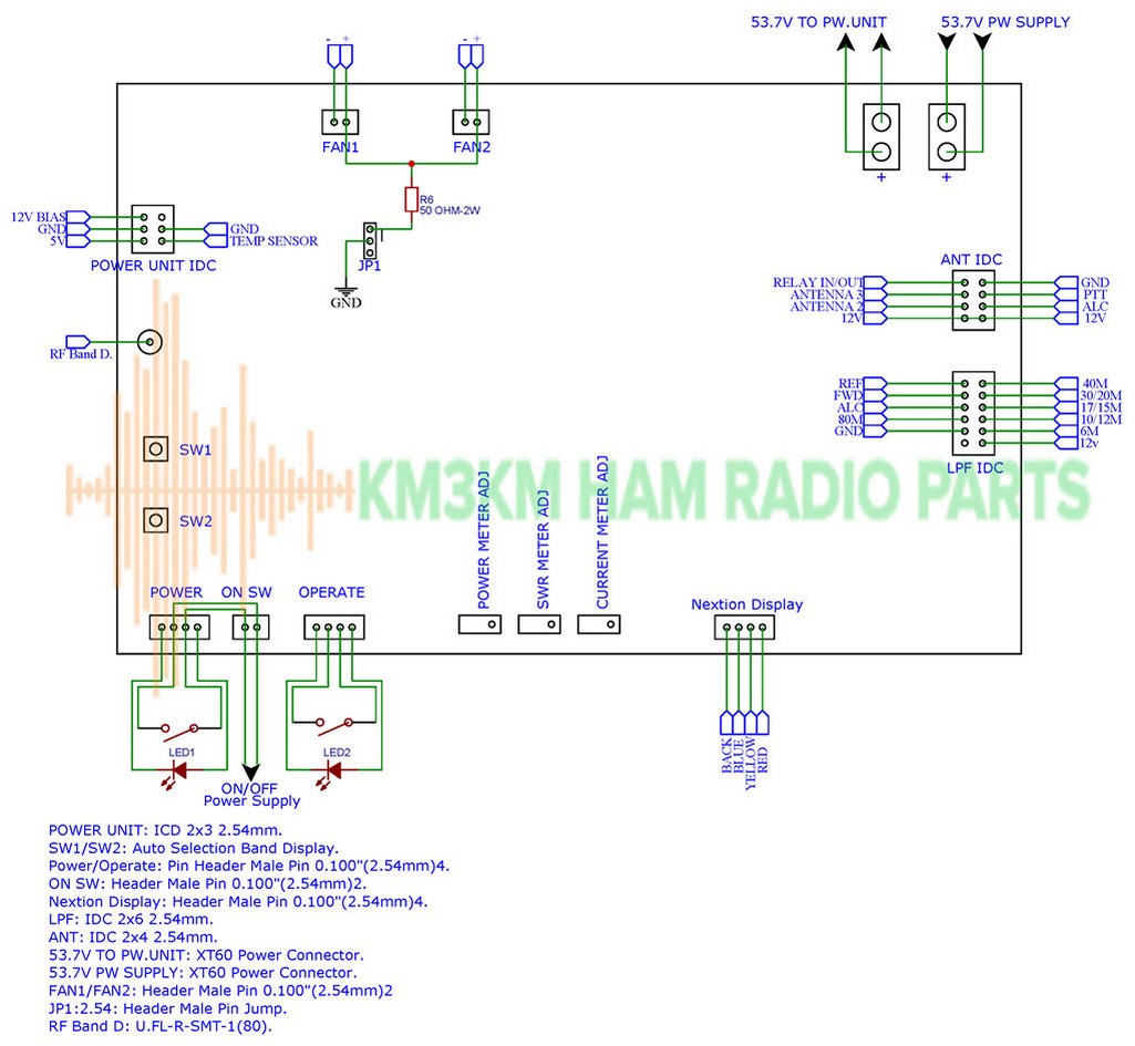
IDC connections
All are compatible with current KM3KM designs, board connections
Voltage sequence
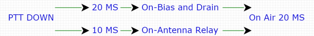
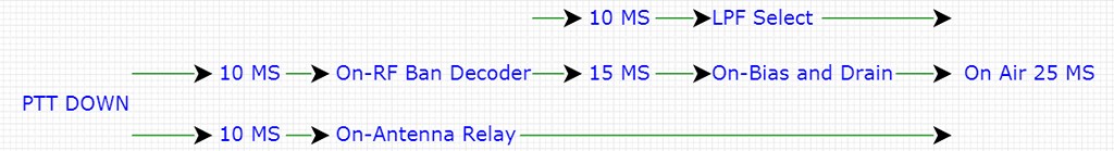
The voltage sequence prevents the relays from burning with an RF arc. Due to the mechanical movement of the relays(GRL2) the delay is 10 milliseconds when the PTT is down, then 12 V Bias and drain voltage is delivered 20 milliseconds after PTT, total time 20 milliseconds (On Air) in Manual Mode. The 8-bit PIC micro controller detects the frequency and connects the LPF relays, after 15 milliseconds it connects the 12 V Bias and drain voltage, total time 25 milliseconds (On Air) in Automatic Mode. I measured the delays wit an oscilloscope, but this effect can be seen with a high speed camera. The led indicates the voltage delivery after relay sound. Video
Note that in SSB mode the radio will not emit RF without modulation, 200 milliwatts are required to detect the operating band. Most radios inpulse RF with PTT click, this is enough.
Manual Band Select time sequence:
Auto Band Select time sequence:
Price
To order, or write a message...